
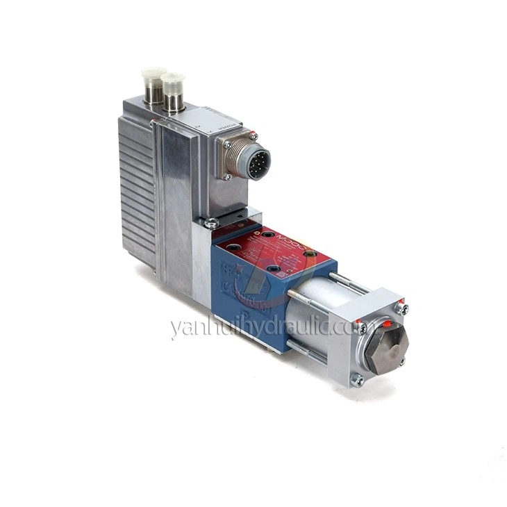
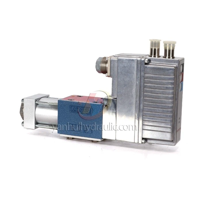
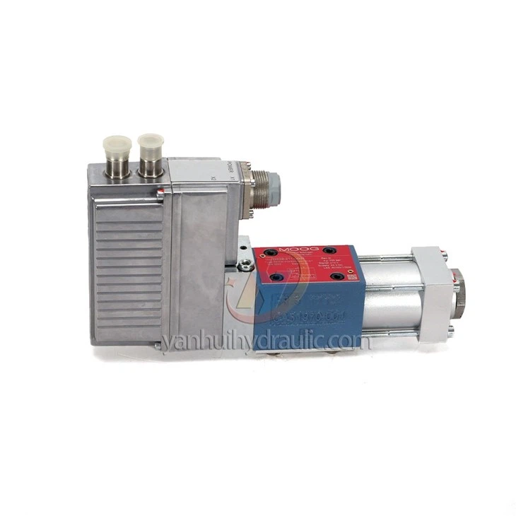
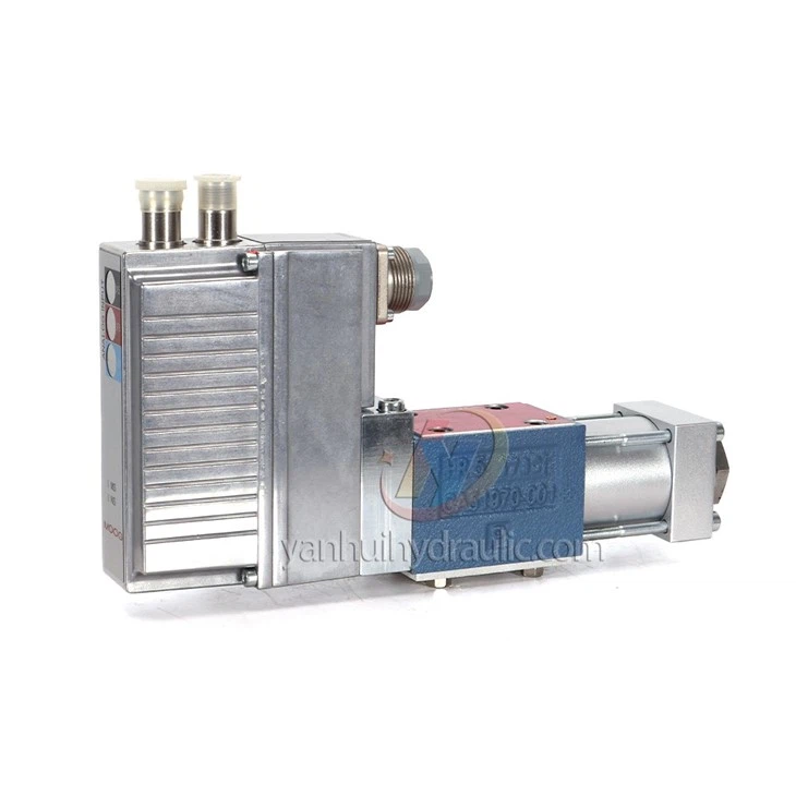
Flow Control Hydraulic Servo Valve D638

Description:
share:
Product Details of Flow Control Hydraulic Servo Valve D638
| Parameter / Specification | Value / Description |
|---|---|
| Valve type / Construction | 1-stage direct-drive servo valve with spool & bushing |
| Mounting pattern | ISO 4401 Size 03 (NG6) |
| Weight | ~ 2.5 kg (5.5 lb) |
| Operating pressure (Ports P, A, B) | Up to 350 bar (5,000 psi) |
| Tank port pressure (Port T) | Without leakage port (Y): up to 50 bar (725 psi); with leakage port Y: up to 350 bar (5,000 psi) |
| Rated flow (per spool land, Δp = 35 bar / 500 psi) | 5, 10, 20, or 40 l/min (1.3–10.6 gpm) depending on model variant |
| Maximum flow | 75 l/min (≈ 19.8 gpm) |
| Step response time (0 → 100 % stroke) | ~ 8 ms (typical) |
| Control functions supported | Flow (Q), Pressure (p), Flow & Pressure (p/Q), Pressure-compensated flow, Axis control (position, velocity, force) |
| Electrical supply voltage | 24 V DC (range 18 – 32 V DC) |
| Control signal options | ±10 V, ±10 mA, 4–20 mA (analog) — plus optional fieldbus interface (CANopen, EtherCAT, PROFIBUS-DP) |
| Fluid / Oil specifications | Hydraulic oil per DIN 51524 (parts 1–3) or ISO 11158; typical viscosity 15–100 mm²/s (cSt) at 38 °C; permissible viscosity range 5–400 mm²/s. |
| Operating temperature range | Ambient: -20 to +60 °C; Storage: -40 to +80 °C |
| Vibration / Shock resistance | Vibration: 30 g, 3-axis, 10 Hz–2 kHz; Shock: 50 g, 6 directions |
| Mounting surface requirements | For maximum flow: port holes Ø 7.5 mm (0.30 in), minimum mounting surface evenness 0.01 mm over 100 mm, surface roughness Ra < 0.8 µm |